
Building a custom ergonomic keyboard
I’ve always wanted an ergonomic keyboard, but the price has always been a barrier. Good alternatives, like the Kinesis Advantage, are expensive where I live. Then, after searching for cheaper alternatives, I discovered the Ergodox Keyboard.
The Ergodox keyboard is an open-source, fully customizable, ergonomic keyboard. You can buy it fully assembled from several sources, or you can build your own. I decided that it would be a great hobby project to build my version and I’ll document the process in this post.
Requirements
To build the Ergodox keyboard you need to have an entry-level knowledge of electronics and good soldering skills. The parts can be sourced from a lot of places. The items below features all the parts and tools you need:
Tools
- Soldering iron
- Electronics solder and flux
- Multimeter
- Electronics tweezer
Components
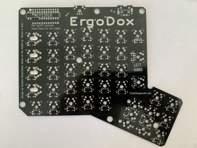
- 2x Blank Ergodox PCBs
- 1x Teensy 2.0
- 1x Microchip`s MCP23018-E/SP
- 76x SOD-123 SMD Diodes
- 2x SJ-43514 3.5mm Jack
- 1x WM17115-ND USB Connector
- 1x 0.1uF Ceramic Capacitor
- 2x 2.2k Ω resistors
- 3x 220 Ω resistors
- 3x T1 LEDs
- 2x USB mini cables
- 1x male-male TRRS cable
- 76x Cherry MX (or compatible) switches
- 1x Ergodox Case
- Keycaps
The case
There are a lot of options you can find for your keyboard case. You can even build your own if you have access to a laser cutter or a 3D printer. The laser cut acrylic case is the cheapest alternative. However, I decided to spend a little bit more and get a bamboo case manufactured by falba.tech. They are lightweight, sturdy, and very aesthetically pleasing.
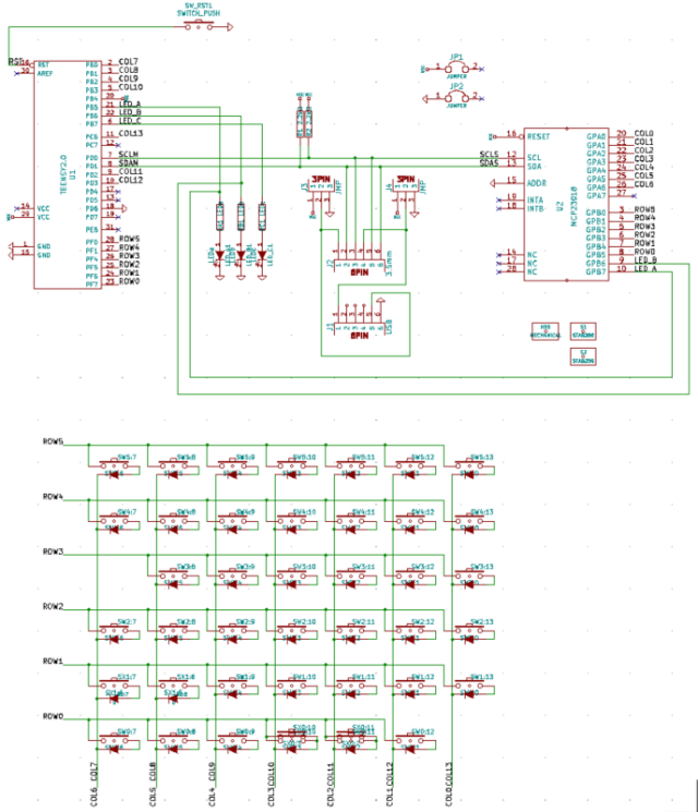
Schematics
The Ergodox design is pretty simple. Each side has a 6x7 switch matrix connected to the Teensy or the MCP23018 IO Expander. The sides are connected via I2C by the TRRS cable. Here is the keyboard’s schematics:
Step-by-step assembly instructions
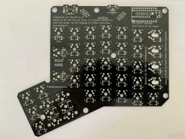
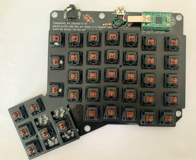
Both Ergodox PCBs are exactly the same. The plane where you mount the components will define the left or right side. Components are mounted on the side they are drawn. You should mount the Teensy on the right side and the MCP23018 on the left side.
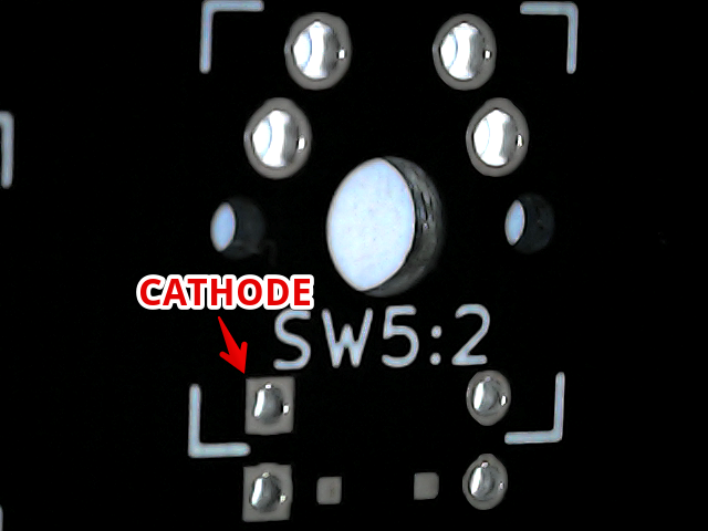
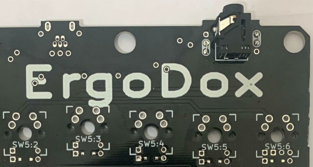
I’ve started with the laborious task of soldering the diodes. The diodes are mounted on each side’s back, with the cathode pointing to the square pad.
A line identifies the diode’s cathode. You might need a magnifying glass to see it. You can also use the multimeter to check the correct orientation.
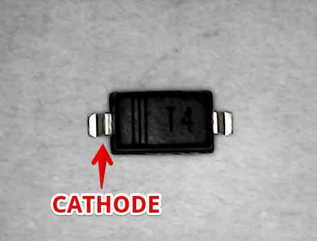
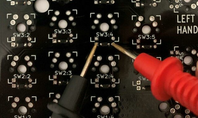
After soldering all the diodes, use the multimeter to test if each diode is soldered correctly. The multimeter’s black probe should go on the square pad.
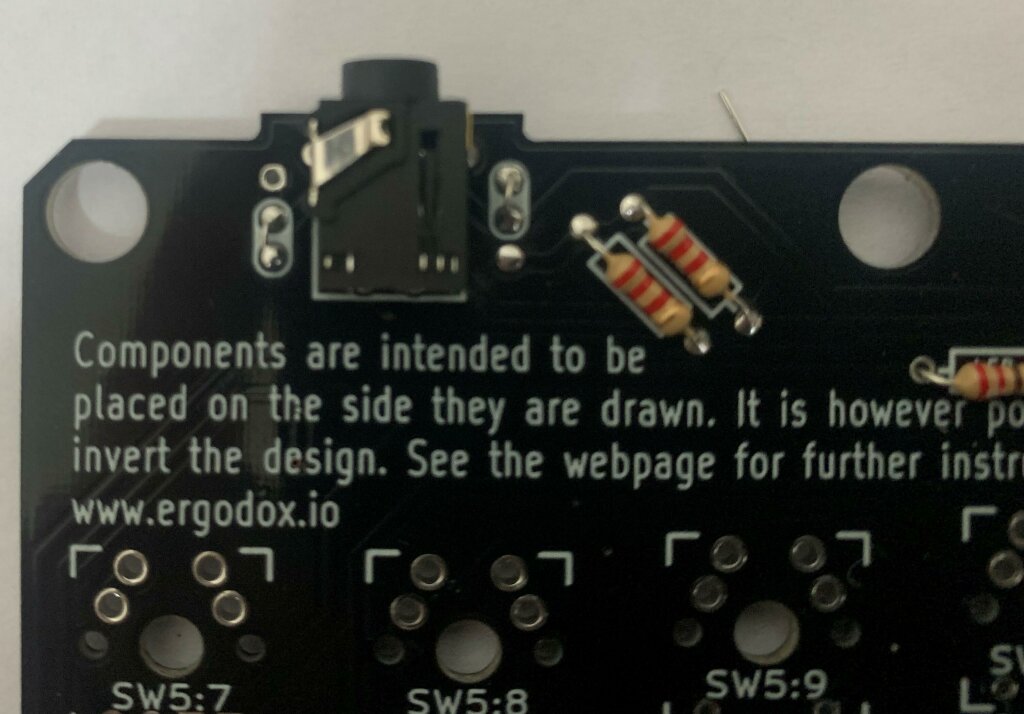
The next step is to solder the resistors and connectors on the front side of each board.
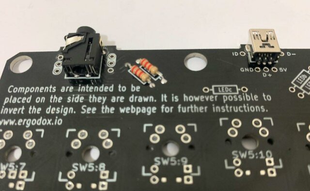
On each TRRS connector, bridge the pads as indicated by the drawing on the PCB.
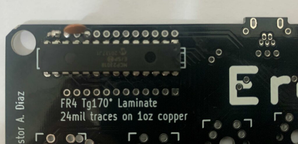
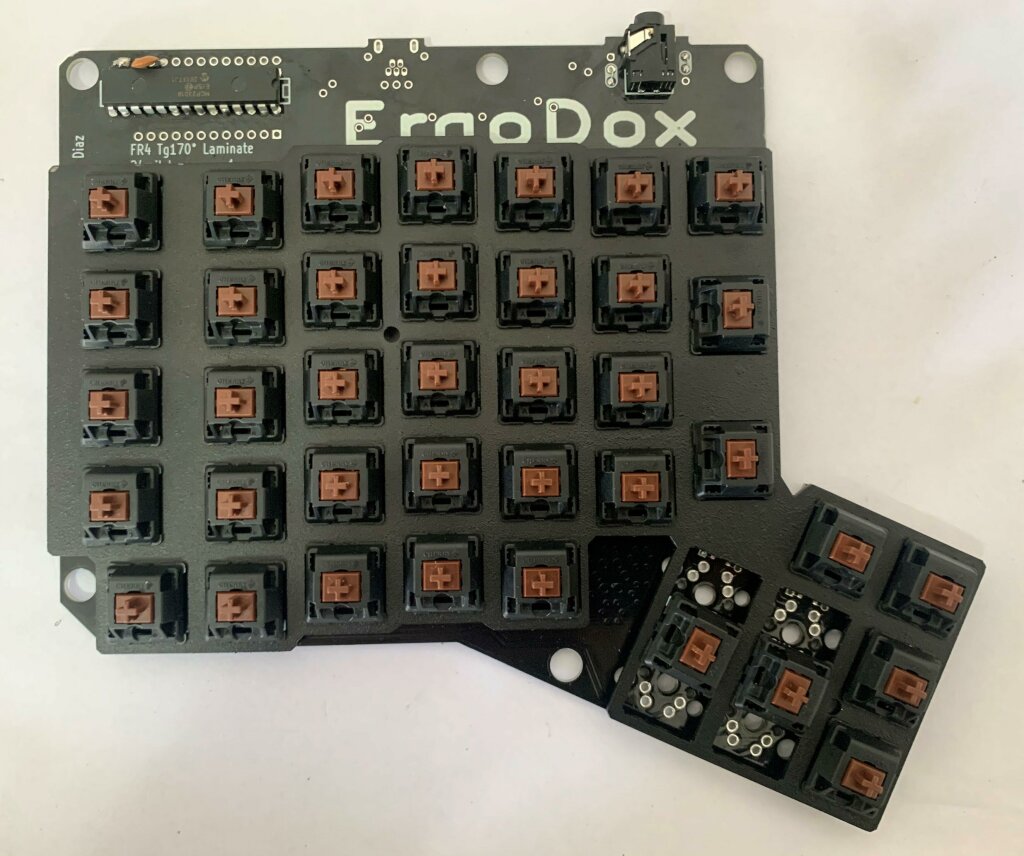
Now we should solder the MCP23018 on the left side. You should also solder the ceramic capacitor on the first and third pad right above the IC. Don’t forget to bridge the two pads on the left upper side.
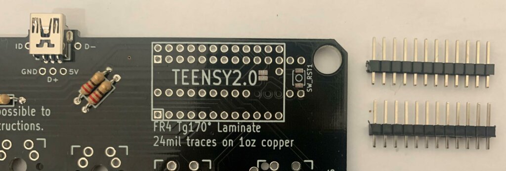
The next step is to connect the Teensy 2.0 to the right side. My Teensy came without pins. So I’ll first solder the jumper wires to the board:
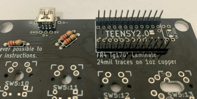
And then connect the Teensy with the USB connector facing inward.
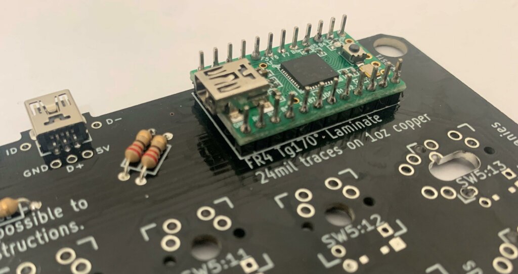
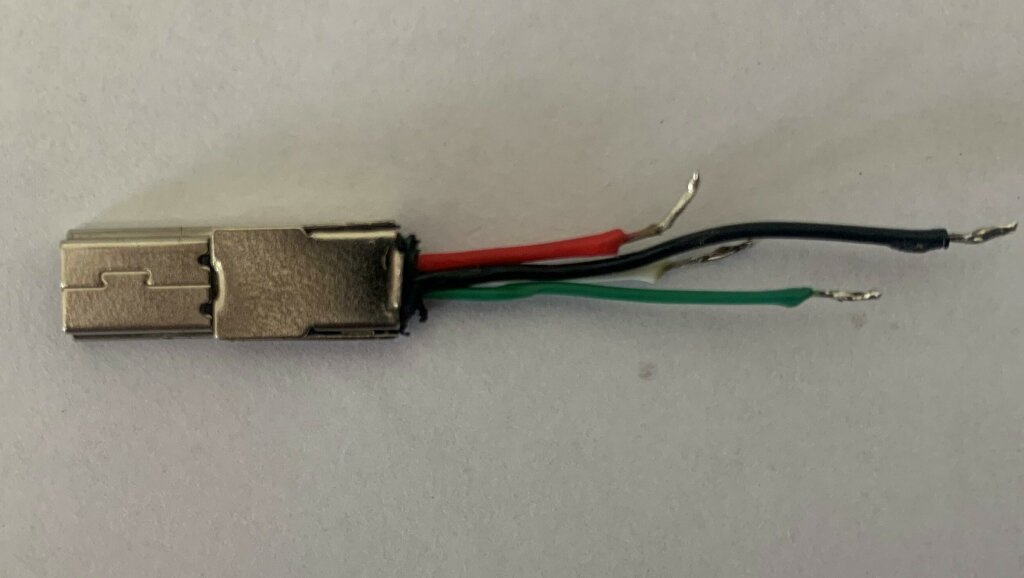
To connect the Teensy to the board, we will cut and peel an existing USB mini cable. Inside the cable, you are going to find the following wires:
| Color | Pad |
|---|---|
| Black | GND |
| Red | +5V |
| Green | D+ |
| White | D- |
Cut each wire to the appropriate size to connect it to the corresponding pad of the PCB.

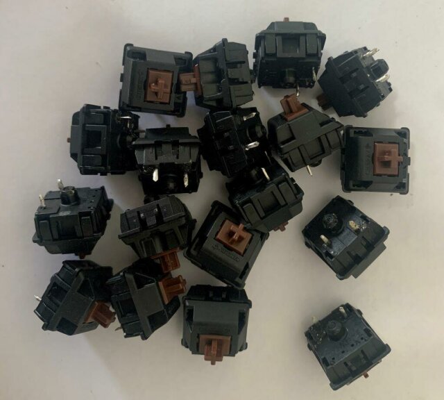
Now I’m going to solder the MX Switches. I’m using some brown MX switches I’ve removed from an old mechanical keyboard.
My case came with a metal plate, so first I will assembly each switch to the plate and then solder the set to the PCB.
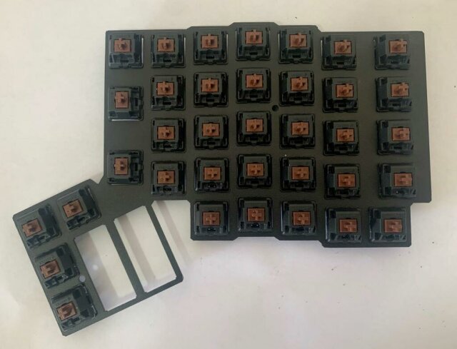
The three switches on the first column of the right side should have the T1 LEDs assembled to them. Remember that LEDs are diodes and have an orientation, the cathode (shorter leg) of the LED should be soldered on the square pad.
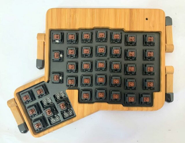
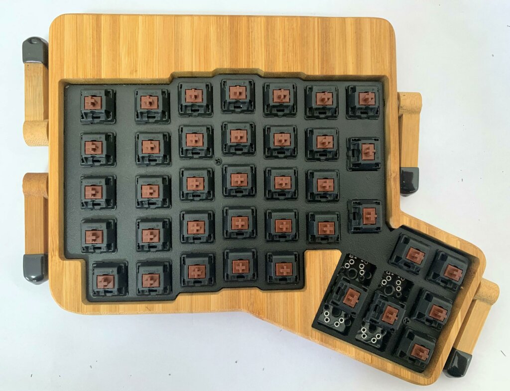
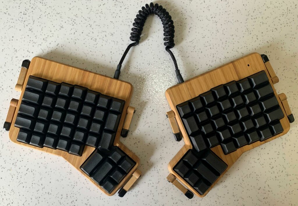
Now I’ll assembly the PCBs to the bamboo case I bought from falba.tech. The picture below shows the partially assembled keyboard without the keycaps:
And below is the fully assembled keyboard with keycaps:
Software
Here is the part where the Ergodox keyboard shines. You can flash it with the open-source QMK firmware and have advanced features that few commercial keyboards provide, like custom layouts, macros, layers, and mouse emulation.
Before flashing the firmware, we should download and install the Arduino IDE and the Teensy plugin.
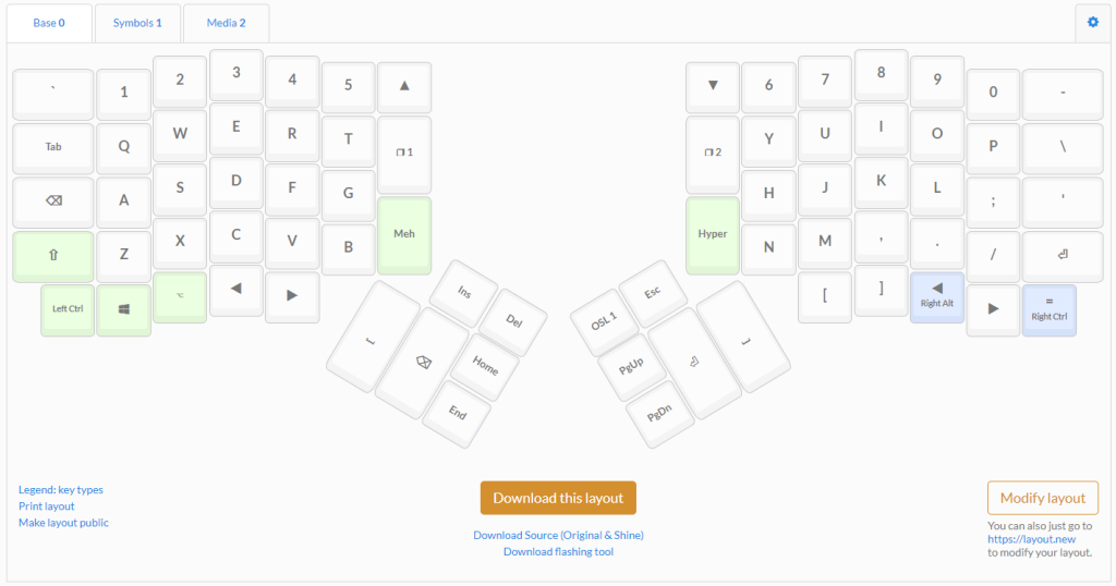
Instead of compiling and flashing my own firmware, I used the Oryx Configurator provided by Ergodox-EZ. You can use it to generate a .hex file that will be flashed to the keyboard. The Oryx tool has a great UI that allows you to customize your own layout and keyboard’s features and is fully compatible with the open-source Ergodox.
After downloading your firmware file, open the Arduino IDE select the .hex file on the Teensy Flashing Tool and press the reset button on the Teensy to start the flashing process.
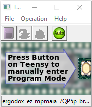
After the flashing process ends, the keyboard should start working.